Article contents 18 sections
To measure an existing door for a smart lock, record five things: the finished door thickness at the lock, the footprint of the old front and rear hardware, the size and position of every hole, the lock-edge cavity and faceplate recess, and any repairs. Measure each from a named face or edge, and pair each critical dimension with a photo.
That record lets you compare the door with the drawing of the lock you are considering, so a thickness match or a bigger front panel is not mistaken for a fit.
The sequence:
identify the door → define the reference faces → measure the finished leaf → map the existing preparation → pair dimensions with photos → record uncertainty → compare with the exact model drawing
Any repair or alteration the door needs is for the installer or door fabricator to review.
Start With One Door ID
Give the opening a stable Door ID before measuring anything.
For one house entrance, Main Entrance is enough. For a hotel, apartment project, office, gate project or replacement program, use a structured identifier such as:
B2-F03-D017
Use the same Door ID on every measurement, photo, sketch and reply, so dimensions from one door never end up next to photos of another. Measure similar-looking doors one by one; their cutouts can differ.
Door construction, opening direction, frame condition and project requirements are covered in the wider smart lock door compatibility: what to measure guide.
Define the Reference Faces Before You Measure
Every dimension needs a start and an end point. Label the surfaces once and use the labels throughout:
| Label | Meaning | Typical use |
|---|---|---|
| F | Front / approach face | Front panel footprint, visible holes |
| R | Rear / inside face | Rear panel footprint, interior obstructions |
| E | Lock edge of the door | Edge-to-center dimensions, mortise/cavity location |
| T / B | Top / bottom datum, where holes sit at different heights | Vertical location of holes or features |
Name each measured relationship precisely, for example M2: lock edge E to the center of the upper through-hole, and write the value and unit beside it.
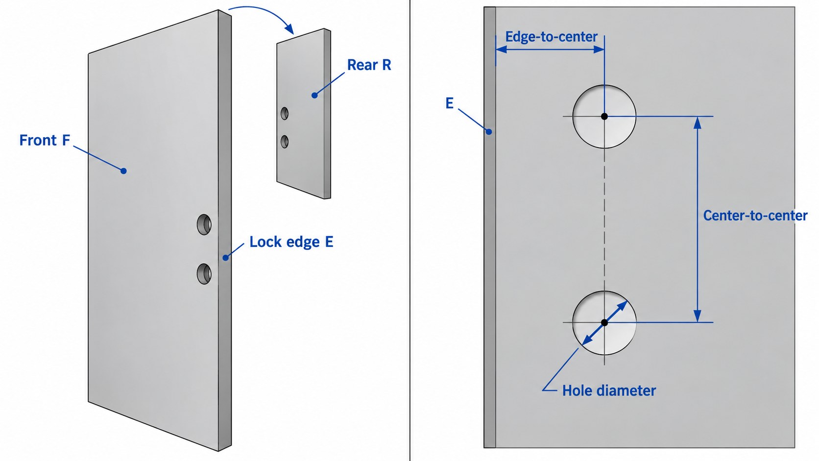
“Upper hole: 60” could be a diameter, a distance from the edge or a spacing from another hole. The label removes that doubt.
Measure from the door, not the trim
Escutcheons, cover plates and moldings can hide the real opening. Tie the dimensions that control fit to the door face, the lock edge or marked hole centers. If the preparation is still hidden, record it as hidden.
On a beveled, rebated or stepped lock edge, show which edge line and which face you measured from. The front and rear readings can differ; record both.
Measure the Finished Door Thickness at the Lock Location
Measure the finished leaf thickness where the smart lock will be mounted: the rigid door with its permanent skins, cladding, metal plates or laminate, at the lock height. A nominal sales thickness, the core, a reading taken elsewhere on the leaf, an old door schedule or an exposed edge can all give a different number.
Leave compressible weather seals out of the thickness.
If thickness varies, take more than one reading
Repaired, clad, tapered, reinforced, overlaid and older doors often vary across the lock area. Take several readings, label them M1A, M1B, M1C, and show each location in the photo with the tool you used.
Use a tape, ruler or caliper only where it sits square, and record precision that matches the tool.
Thickness is the first screen; the cutout checks below decide the fit.
Keep units and conversions explicit
Use one main unit and write it beside every value. If the original reading is in inches, keep it and mark the millimeter value as a conversion. A reading of 1¾ in converts to 44.45 mm; the tape read to about a millimeter, so record 44.5 mm or 45 mm.
If the ruler, a drawing and an old data sheet disagree, keep all three and measure again. Never pick the value that happens to suit the new lock.
Record the Existing Panel Footprint Before Looking Only at Holes
The old lock leaves two kinds of evidence:
- the visible footprint of the old front and rear hardware;
- the openings underneath it.
Record both. For the front and rear faces, photograph and note:
- old panel or escutcheon width and height;
- stain, paint line, wear mark, or indentation left by the old panel;
- nearby trim or molding;
- reinforcement plates;
- old screw holes;
- obstructions that would stop the new panel sitting flat.
Whether a larger new panel covers the old holes comes down to the new panel's real footprint, the hole pattern, the edge distances and fixing points, and the surface around them. Our A2 panels are 353 × 73 mm and the A11 panels 290 × 40 mm, so an old footprint wider than 40 mm stays visible beside an A11. “The new panel looks bigger” is a reason to measure.
On glass doors and narrow aluminum stiles, the flat surface beside the glass or bead is often the limit; see glass door vs aluminum profile fitment.
Map the Existing Holes and Cutout
Once the preparation is visible, make a simple field map. It only has to be unambiguous:
| Existing feature | What to record | Why it matters |
|---|---|---|
| Through-hole / bore | Center, diameter or shape, F/R relationship | Shows whether new trim and fasteners land on old holes or fresh material |
| Spindle hole | Center and opening shape | Compared with the new lock body's spindle position |
| Cylinder hole | Center, outline, side | Compared with the new cylinder and mortise arrangement |
| Screw holes | Center, diameter/slot, condition | Shows where the old fixing pattern overlaps the new one |
| Cable hole | Position and visible condition | Sets the cable route between the two panels |
| Edge cavity / mortise pocket | Visible width, height, accessible depth | Compared with the exact lock body |
| Faceplate recess | Boundary and accessible depth | Compared with the new faceplate |
| Latch / bolt openings | Visible positions and shape | Helps compare door-edge and frame-side geometry |
| Abandoned holes | Size, location, condition | Coverage and remaining material |
| Repair / filler / weld | Boundary and condition | Flags a possible adaptation |
| Reinforcement plate | Position and relationship to holes | Can affect fixing and clearance |
Where old hardware still covers the opening, mark the field Unknown or Insufficiently exposed instead of guessing.
Measure Centers, Not Just Edges
Measurements only compare when everyone measures to the same point, and centers are the reliable one.
For a round hole, measure the diameter across its widest part. Find the midpoint between opposite edges, check it in a second direction and mark the center on the photo or sketch. Measure edge-to-center square to the reference edge; a diagonal reading comes out long.
Also fix each hole vertically, from a named horizontal datum or from another labeled center, using the same datum for every hole on that face. Record the rear face separately when its openings differ from the front.
Write it as:
E to center of spindle hole
or:
Center of spindle hole to center of cylinder hole
instead of a bare “hole spacing”.
Edge-to-center is different from center-to-center
Three different measurements:
- edge-to-center: from a named structural edge to a labeled hole center;
- center-to-center: between two labeled centers;
- hole diameter: the size of the opening itself.
For a slot or irregular opening, record width, height, orientation and outline. On an enlarged hole the original center may be gone: say whether your center comes from the visible outline or from identifiable hardware or a drawing, and show the opening in the photo.
Check What the Old Trim Hides
Behind an old panel there may be:
- additional holes;
- slotted or enlarged openings;
- an adapter plate;
- an old repair;
- welded patches;
- a second abandoned pattern;
- thin remaining material;
- a mortise cavity that is larger than expected.
If the hardware cannot be removed yet, keep what you saw separate from what you assume:
Front panel footprint: observed. Finished thickness: measured. Upper through-hole: unknown, hidden by existing trim. Edge cavity: partly observed. Repair history: unknown.
That record is far more useful than calling every hidden field “standard”.
Record Repairs, Filler Plates, and Enlarged Openings
A repaired door can still take a smart lock, as long as the repair is on the record. Note:
- welded patches;
- filler or adapter plates;
- elongated holes;
- enlarged bores;
- overlapping old holes;
- abandoned screw patterns;
- cracked wood;
- crushed or thin material;
- reinforcement plates;
- previous re-drilling.
For each one, show:
- where it is;
- how large it is;
- how it relates to the proposed lock area;
- whether the material underneath is visible;
- whether it needs checking against the lock drawing.
How to weld, fill, redrill or repair the door is for the installer or fabricator to decide.
Pair Every Critical Measurement With a Photo
Give each measurement and its photo matching IDs. For Door ID D017:
| Measurement ID | Measurement | Photo ID | What the photo should prove |
|---|---|---|---|
| D017-M1 | Finished thickness at lock location | D017-P1 | Tool, both faces, actual lock rail |
| D017-M2 | E to center of upper through-hole | D017-P2 | Lock edge, marked center, scale |
| D017-M3 | Center-to-center between two holes | D017-P3 | Both labeled centers in same plane |
| D017-M4 | Old panel footprint | D017-P4 | Full boundary and surrounding surface |
| D017-M5 | Edge cavity | D017-P5 | Lock edge, cavity boundary, faceplate recess |
| D017-M6 | Repair / filler condition | D017-P6 | Repair area plus wider context |
Any naming scheme works, as long as each number leads to its photo.
Use an overall view and a close-up
For each critical feature, take:
- one wider photo showing where the feature sits on the door;
- one close-up showing the ruler, center mark, hole, repair, or cavity.
Keep the reference edge in the frame, lay the ruler flat against the feature, and measure depth with a tool instead of judging it from a photo. Photos support the measurement; the number still comes from the tool.
Example: a useful record can still contain unknowns
A measured field and a hidden field can sit in the same record:
Door ID: D017; F = corridor face; R = room face; E = lock edge.
D017-M1: finished F-to-R thickness at the lock location = 45 mm (inside the 40–120 mm range of our A2 IP66 waterproof smart lock and the 40–90 mm range of the A11 profile door smart lock); measured with a ruler; photo D017-P1 shows the reading and location.
D017-M2: E to center of exposed upper circular hole H1 = 60 mm; measured on F; photo D017-P2 shows E, H1, and the scale. H1's vertical location is marked on the accompanying sketch.
Lower fixing holes: unknown; rear trim remains installed.
Next check: document the hidden preparation before requesting a final fit decision.
The two measured values are enough for a first review; the lower holes are the one open item before a final answer.
Record How Each Value Was Obtained
Tag each field:
- Measured: read directly from the existing door with a stated tool.
- Drawing: taken from an identified drawing; note whether it matches the installed door.
- Observed: visible in a photo or on site, but not measured.
- Estimated: an approximate value that still needs checking.
- Unknown: hidden, inaccessible, or not yet established.
For a complete record, add:
- tool used;
- units;
- one-point or multi-point measurement;
- accessible or hidden;
- hardware removed or still covering the area;
- paired photo ID;
- rounding, measurement uncertainty, or variation between readings;
- recheck needed: yes/no.
“I measured this opening” and “the old lock looks like a common size” are very different statements, and the tags keep them apart.
Check for Retrofit Problems Before Ordering
End the record with one of four labels:
| Status | Meaning | Next action |
|---|---|---|
| Measurement ready | Reference faces, critical dimensions, and photos are clear | Compare with the exact model drawing |
| Drawing review needed | Geometry is visible, but needs checking against the model drawing | Hold release until the review is back |
| Adaptation risk | Repairs, overlapping holes, reinforcement or thin material that could need rework | Review with the drawing and the installer or fabricator |
| Insufficiently exposed | The real opening is still hidden, contradictory, or not measurable | Expose or clarify the opening first |
The labels rate the record; the lock is judged later, against the drawing:
Is the existing opening documented well enough for the next technical review?
Record Lock-Body Geometry for the Drawing Check
Record the edge cavity, faceplate recess, spindle and cylinder holes, backset and center relationships as physical facts. Then compare them with the lock body and preparation drawing of the model you are considering, including when an existing lock body is meant to stay.
Two locks can share similar headline measurements and still differ in case depth, faceplate, latch and bolt arrangement, spindle or cylinder interface, or door preparation, so a matching center distance does not settle the rest of the fit. Our A2, for example, takes 6068, 4585, Russian 6585 or Russian 6085 bodies, and A11 profile bodies from 2585 to 7085, each with its own case and faceplate.
How to read those two numbers is in backset and center distance, and how to name the old body in identify an existing mortise lock.
The Exact Model Drawing Controls the Final Comparison
Preparation drawings are model-specific. Schlage's L-Series collection has separate templates by lock function, trim and wood or metal door, and its lock-case sheets give case size, backset, door range and center relationships, marked not to scale. [1]
Compare your measurements with the current drawing or template of the model and variant you are considering, note its revision, and read the labeled dimensions instead of scaling the drawing. A thickness range, hole pattern, mortise or template belongs to one model only.
What to Include in the Measurement Pack
Before sending the question “will this smart lock fit?”, put together one compact pack:
- Door ID;
- door construction/type;
- named F/R/E reference faces;
- finished thickness at the actual lock location;
- multi-point thickness if variable;
- front and rear old-panel footprints;
- labeled existing holes;
- hole diameters and shapes;
- edge-to-center dimensions;
- center-to-center dimensions;
- visible edge cavity and faceplate recess;
- abandoned holes;
- repair/filler/reinforcement conditions;
- paired photos for critical dimensions;
- measurement-confidence status;
- handing field from the existing door record;
- candidate smart-lock model/variant;
- open fields.
For one door, a labeled sketch, a measurement sheet and a few paired photos are enough. For a replacement program, keep each door's record together and mark any measurements shared across doors you have checked to be identical.
What the Drawing Check Answers
| You record | The drawing check answers |
|---|---|
| Finished door thickness | Whether it is within the exact model/configuration range |
| Existing holes and centers | Whether they align with the required preparation |
| Panel footprint and damaged/old areas | Whether the new panel covers and seats correctly |
| Edge cavity and faceplate recess | Whether the selected mortise/lock body is suitable |
| Repair/filler/reinforcement | Whether adaptation review is required |
| Photo-measurement evidence | Whether any critical geometry is still missing |
| Candidate model/variant | Exact drawing/template revision controlling the review |
Frequently Asked Questions
Should I remove the existing lock before measuring?
If you are allowed to and it can be done safely, yes: the preparation underneath is what the new lock has to match. Otherwise, mark the hidden fields as unknown.
Can a larger smart-lock panel cover my old holes?
Often, yes. Where the old holes are, the new panel's footprint and fixing pattern, the edge clearances and the material left around them decide it, so measure those before relying on it.
Should I measure backset and center distance?
Yes, where you can identify them, naming the edge and centers used. Mortise fit also depends on the complete lock-body geometry, which is compared with the model drawing.
What if the old cutout cannot be fully exposed before ordering?
Collect what is visible and list exactly which fields are still hidden. A first review can go ahead; the final fit answer waits for those fields.
Prepare the Opening Record Before Choosing the Lock
Existing doors are misjudged when a few dimensions arrive without showing where they came from. The reliable method:
Door ID → named reference faces → finished thickness → labeled holes and cutout → repairs/hidden conditions → paired photos → confidence status → exact-model drawing review
With that record and the model you are considering, we tell you which drawing applies, which existing features work with it, and what still needs checking before purchase.
References
- Schlage / Allegion. L-Series Door Template Index, Door Preparation Templates, and Lock Case Dimensions. See the template index and lock-case sheets L1–L2 for product-specific geometry and the not-to-scale notice.